
Welcome to Ram
Meenakshisundaram's Transputer Home Page
"…sequential computers are
approaching a fundamental physical
limit on their potential power. Such a limit is
the speed of light…"
Sundance SMT004A-2 4 Slot PC/ISA TRAM Motherboard
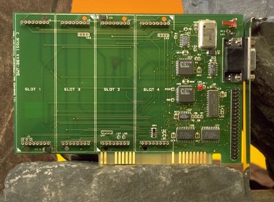
- 4 TRAM slots
- Half-card format
- PC AT/XT compatible
- 3 selectable PC I/O addresses
- Switchable link speed
- B004 software compatible
- IMSC011 PC interface
- Slot 1 sub-system reset
- Surface mount construction
- Board mounted pipeline jumpers
- 12 month warranty
- Low-cost transputer development platform
- Host for single processor special purpose TRAMs such as
SMT208A 'C40 TRAM
- Embedded OEM systems
- Hosting up to 8 T805 processors using SMT213 dual processor
TRAMs
- PC host board for remote rack based system using SMT227
fibre optic TRAMs
- Upgradeable entry-level system
- Software application accelerator
- Lap-top based transputer systems
- Compatible with all transputer compilers
The SMT004A-2 is a low-cost, 4 slot TRAM motherboard designed to accommodate
up to 4 transputer modules within a PC/ISA slot and normally occupies
a single half-length expansion slot. The SMT004A-2 offers ’Plug-and-go’
system integration, with a wide range of TRAMs available from Sundance
and other companies. Guaranteed compatibility enables system integrators
to easily configure bespoke solutions to embedded computing problems.
In additions, systems may be installed simply by replacing one or
more of the motherboard’ on-board TRAMs.
The SMT004A-2's interface enables the PC to reset, analyze and communicate
with a network of TRAMs. Links 0 and 3 of each TRAM site is connected
to a 40-way strip.
Reset/Analyze/Error signals of each TRAM site can be connected to
the Up signal from another transputer signal or connected to the PC
bus. Slot 1 has a sub-system port and these signals may be used to
control the remaining TRAMs. Up, Down and Sub-system signals are accessible
from the 40-way strip connector. PC addresses #150 is used for the
8-bit bus interface.
On the SMT004A-2 there is a set of software registers that
perform various control functions required for link communication. They also
allow the user to control the status of external transputer networks.
These registers are mapped as an IO port. The base value is
fixed at #150.
Port IO Map
| Address |
Register |
| Base+0 |
Input Data Register ( ro ) |
| Base+1 |
Output Data Register ( wo ) |
| Base+2 |
Input Status Register ( rw ) |
| Base+3 |
Output Status Register ( rw ) |
| Base+16 |
Error Register ( ro ) |
| Base+16 |
Reset Register ( wo ) |
| Base+17 |
Analyse Register ( wo ) |
These two registers are located inside the C011 chip. The
functions of the input and output data registers are reasonably self explanitory.
When the status registers indicate that they are either ready to receive valid
data, or they contain valid data then the data is written to or read from these
registers.
These registers are contained in the C011 chip and indicate
the status of the input and output data registers.
Input status
| rd |
Bit 0 |
0 |
no input data |
| |
|
1 |
valid input data |
| wr |
Bit 1 |
0 |
disable input int |
| |
|
1 |
enable input int |
Output status
| rd |
Bit 0 |
0 |
output busy |
| |
|
1 |
output ready |
| wr |
Bit 1 |
0 |
disable output int |
| |
|
1 |
enable output int |
The source and desitination of the Reset, Analyse and Error
signals is determined by the presence of the resistors LS4 and LS5. For more
details refer to the Sub-system control section.
The error status is a software readable port that indicates
the Error status of the external transputer network. It can either be the error
line from the error pin on Slot 1, or the UpNotError line from the 40-way patch
area on the board.
Error Register
| rd |
Bit 0 |
0 |
Error false |
| |
|
1 |
Error true |
You can write to this register to control the state of the
PCNotReset line on the 40-way patch area. This can then be used to control an
external transputer network. Normally these signals are fed back onto the
SMT004A-2 to control any TRAMs that are fitted.
Reset Register
| wr |
Bit 0 |
0 |
Reset false |
| |
|
1 |
Reset true |
You can write to this register to control the state of the
Analyse line of the onboard transputer, or the PCNotAnalyse line on the 40-way
patch area.
Analyse Register
| wr |
Bit 0 |
0 |
Analyse false |
| |
|
1 |
Analyse true |
This small piece of psuedo-code demonstrates how to access the data
registers on the PC Bus.
    read_byte()

      do

        wait a while

      while((read_status_port AND 1) equals 0)

      read in the input_data_port

      return the data read in


    write_byte()

      do

        wait a while

      while((write_status_port AND 1) equals 0)

      output data to output_data_port
The SMT004A-2 is designed to be a very low-cost board, and as such all
options are pre-configured in the factory by using surface mount resistors.
These functions can be changed by the user if required, or may be returned to
the factory for modification.
The board address is fixed at #150.
Inmos links are capable of operation at two speeds. There are two sets of
resistor pads which allow the user to select the link speed of the bus interface
and the TRAMs independently. LS1 and LS2 are a row of three pads with resistor
being fitted to the centre pad and either the top or bottom pad.
C011 Link Speed
| LS1 |
LS2 |
Speed |
Comment |
| Out |
Out |
N/A |
Does not function |
| Out |
In |
10MBit/s |
Factory default |
| In |
Out |
20MBit/s |
|
| In |
In |
N/A |
Does not function |
TRAM link speed
| LS6 |
LS7 |
Speed |
Comment |
| Out |
Out |
20MBit/s |
|
| Out |
In |
N/A |
Does not work |
| In |
Out |
N/A |
Does not work |
| In |
In |
10MBit/s |
Factory default |
The Motherboard is designed so that TRAM slots 1, 2, 3 and 4 can be
controlled from a variety of sources. For slot 0 there is the option of being
Reset and Analysed by either the PC interface or the Up control lines. The
choice is determined by the presence of resistors at LS4 and LS5. For the other
3 slots there is the choice of being Reset and Analysed by either the Subsystem
port on the first TRAM or the Down control lines.
| Res. |
|
Comment |
| LS4 |
In |
SubSystem active - factory default |
| |
Out |
DownNot active |
| LS5 |
In |
PC interface active |
| |
Out |
UpNot interface active |
Resister LS3 is be used to select the source and destination of the link
information passed through the C011 link adapter. It can be set so that it sends
information to, and receives information from the back connector, or TRAM slot
1. It has to be either one, or the other. It cannot be selected to be both.
| Res. |
|
Comment |
| LS3 |
In |
40-way strip header |
| |
Out |
Slot 1, factory default |
| Pin |
Signal |
Pin |
Signal |
|
| 1 |
Gnd |
21 |
TRAM 4 Link 7 Out |
| 2 |
UpNot Reset |
22 |
TRAM 4 Link 7 In |
| 3 |
UpNot Analyse |
23 |
Gnd |
| 4 |
UpNot Error |
24 |
C011 Link In |
| 5 |
NC |
25 |
Pipe Head Link Out |
| 6 |
NC |
26 |
Pipe Head Link In |
| 7 |
TRAM 1 Link 3 Out |
27 |
SubSystem Not Reset |
| 8 |
TRAM 1 Link 3 In |
28 |
NC |
| 9 |
Gnd |
29 |
SubSystem Not Analyse |
| 10 |
TRAM 2 Link 2 Out |
30 |
SubSystem Not Error |
| 11 |
TRAM 2 Link 2 In |
31 |
Pipe Tail Link Out |
| 12 |
TRAM 2 Link 3 Out |
32 |
Pipe Tail Link In |
| 13 |
TRAM 2 Link 3 In |
33 |
NC |
| 14 |
TRAM 3 Link 4 Out |
34 |
NC |
| 15 |
TRAM 3 Link 4 In |
35 |
Down Not Reset |
| 16 |
Gnd |
36 |
Down Not Analyse |
| 17 |
TRAM 3 Link 5 Out |
37 |
Down Not Error |
| 18 |
TRAM 3 Link 5 In |
38 |
NC |
| 19 |
TRAM 4 Link 6 Out |
39 |
NC |
| 20 |
TRAM 4 Link 6 In |
40 |
C011 Link Out |
To use pipe connections IC7 must be fitted (74BCT125)
LS3 selects C011 connection (PL1 or TRAM Link 0)
Add TRAMs to slot 1 of the SMT004A. The TRAM can be of any size up to a size
4 TRAM. It should have its identifying triangle aligned with the triangle marked
on the SMT004A. If the Subsystem port is to be used (e.g., in an Inmos TDS
system) then the module Subsystem pins should be carefully aligned with both the
sockets provided in the Motherboard and the TRAM.
Any pin protectors fitted to the TRAM should be removed to prevent fouling
the next slot of the PC, and nylon bolts should be fitted to prevent the TRAM
from working loose. All TRAM pin 1 marker Triangles should be aligned with those
on the SMT004A.
Having fitted the TRAMs to the SMT004A-2 as required, make any link
connections between them before installing the assembly into the PC.
Remove all power from the PC, then open the case to expose the expansion
slots. Choose a vacant slot that has sufficient space around it for any special
TRAM modules or cables and remove the blanking plate from this slot, retaining
the screw for fixing the SMT004A. Slide the SMT004A-2 into the relevant slot
ensuring that the 'tail' of the card is in the card guide provided for it. Do
not use excessive force.
When the SMT004A-2 is almost pushed fully home the gold fingers should be
carefully aligned with the relevant connector in the PC and firmly pushed home.
The fixing screw should then be fitted to retain the SMT004A-2 and any casings
replaced on the PC.
Reapply power to the machine and switch on. The machine should boot normally.
If it doesn't it probably means that there is an address clash somewhere. In
this event call Sundance technical support to check that the values selected
with the address jumpers are not clashing with existing cards.
| Ident |
Function/Part Number |
| IC1 |
74F245 |
| IC2 |
PAL22V10 |
| IC3 |
IMSC001 |
| IC4 |
74BCT125 |
| IC5 |
74F14 |
| IC6 |
PAL22V10 |
| IC7 |
74BCT125 |
| IC8 |
74BCT244 |
| X1 |
5MHz Oscillator |
| DB9 |
9-way D-type connector |
| PL1 |
40-way strip header |
| LK1,2,3 |
Pipe jumpers |
| LK4 |
Terminator Jumper |
| J10 |
Custom Interface (Not Specified) |
| Feature |
Unit |
| Format |
PC/ISA |
|
| Size |
Half card |
|
| Number of module slots |
4 |
|
| Module format |
TRAM |
|
| Host interface |
8-bits |
|
| Sub-system logic |
Yes |
|
| On-board processor |
No |
|
| Peripheral logic |
No |
|
| Length |
165 |
mm |
| Width |
105 |
mm |
| PCB thickness |
1.5 |
mm |
| Comp. height above PCB |
10 |
mm |
| Comp. height below PCB |
0 |
mm |
| Storage temperature |
0-70 |
°C |
| Operating temperature |
0-50 |
°C |
| Weight |
65 |
g |
| MTBF |
674,000 |
Hours |
| Power supply voltage |
4.75-5.25 |
V |
| Power consumption |
TBA |
W |
The device is manufactured within the EU. Sundance Multiprocessor Technology
is implementing BS5750 quality control procedures.
Sundance manufactures a range of standard and custom parallel processing
products. The company strives to produce a comprehensive range of sub-system and
system level products at high-quality and at a competitive price.
In line with a policy of continuous product development Sundance reserves
the right to alter these specifications without prior notice. No responsibility
can be accepted for loss or damage arising from the use of this product or
documentation. Any comments on inaccuracies, omissions or structure of this
document would be gratefully received via fax.
Sundance offers a 12 month warranty on this product. The terms of this
warranty are that the product be returned to the manufacturer or distributor
from which the product was purchased. Repair or replacement will be chargeable
if the failure is as a result of either electrical or mechanical misuse.
Please contact Sundance to check that this revision of the engineering data is
current with the latest revision of the printed page version.
This page is copyright ©1995, Sundance Multiprocessor Technology Ltd.
